Both P20v2 and P42 PCBs have net errors with its rotary encoders. Pin Bs and GNDs were interchanged. Removing PCB traces and re-wiring new ones will correct these.

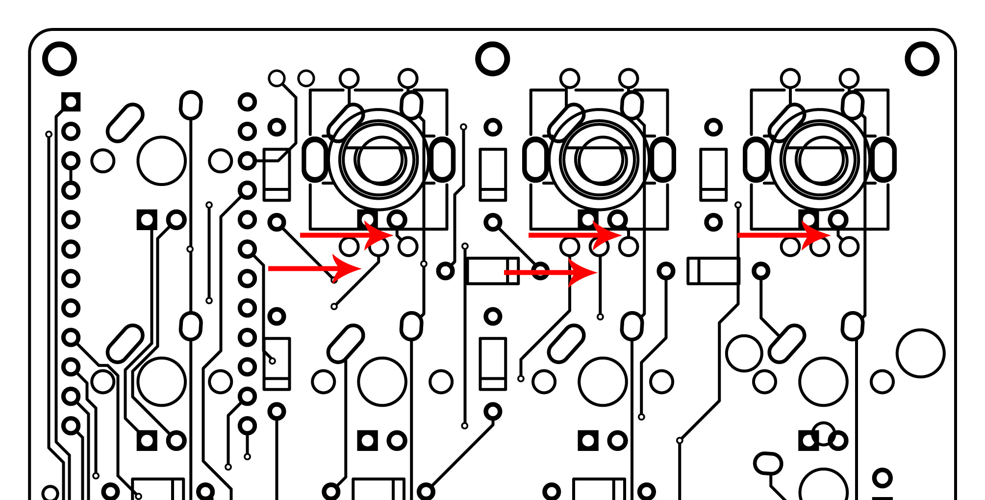
Front of PCB


First, these are the current pin outs for P20v2 PCB (A C B):
Encoder 0: F4 F7 GND
Encoder 1: F5 B1 GND
Encoder 2: F6 B3 GND
Above pins should be:
Encoder 0: F4 GND F7
Encoder 1: F5 GND B1
Encoder 2: F6 GND B3
Disclaimer: These steps may cause shorts, kill the PCB, or cause personal and/or property damage. Please proceed at your own risk.
Now that the proper pins were identified, we now have to remove existing trace/nets/connections of the encoders. I use a small knife to cut the traces:

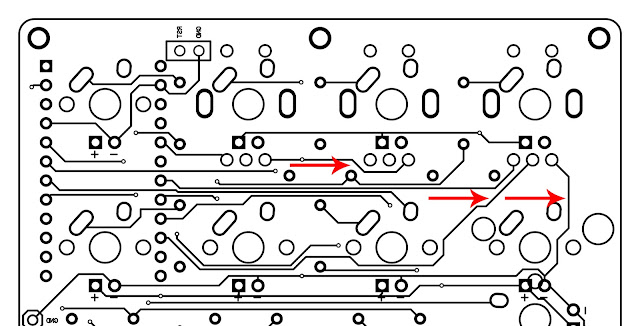
The traces that needs to be disconnected are those shown in the following photos:
Back of PCB

Photos of disconnected traces on mine:


Now that the connections were cut, it's time to place the traces to their proper pins.

Actual photos

...and here's a view from the back:

Middle pins of the encoders should all be connected to GND.
To activate these encoders, edit ver2/config.h and add the following:
#undef ENCODERS_PAD_A #undef ENCODERS_PAD_B #define ENCODERS_PAD_A { F4, F5, F6 } #define ENCODERS_PAD_B { F7, B1, B3 }...then define roles of the encoders in ver2/keymap.c
void encoder_update_user(uint8_t index, bool clockwise) { if (index == 0) { /* First encoder */ if (clockwise) { tap_code(KC_A); } else { tap_code(KC_B); } } else if (index == 1) { /* Second encoder */ if (clockwise) { tap_code(KC_C); } else { tap_code(KC_D); } } else if (index == 2) { /* Third encoder */ if (clockwise) { tap_code(KC_E); } else { tap_code(KC_F); } }}
Compile. Flash. Enjoy!
Is this applicable to P20v4 pcb?
ReplyDeleteno. but you will need to jump these pins for encoder 0 https://pabileonline.blogspot.com/2020/10/p20ver3.html
Delete