
Preparation
It is best that these materials, components and tools are rechecked, inspected, and, within arms reach before assembly. Make sure that all materials, components, tools and working area are clean and free from defects. Review and observe safety measures at all times.Each P40_Ortho keyboard kit contains the following:
- P40_Ortho PCB
- P40 Top Plate
- 1 set Pro Micro controller with pin headers
- 40 pieces Diodes
- 1pc Reset Button (update 20210206)
- 5 pieces case screws
- 1 3D printed casing
- (Up to) 40 MX or Alps compatible switches and keycaps
- Optional 2u PCB or plate mount switch stabilizer for MIT layout
- USB micro data cable
Tools required in assembling P40 do-it-yourself keyboards:
- Soldering iron and solder wire/lead
- Wire (flush) cutter / snips
- Cross-head (precision) screw driver
- Insulation / electrical tape
- Cleaning (tooth)brush
- Tweezers
- Optional solder sucker
- Optional switch and keycap puller
- Optional solder helping hand or small clamps
P40_Ortho PCB
Below is an illustration of the PCB (version P40O-01i).

Components
Testing the controller.
All Pro Micro controllers released with the kit are pre-installed with QMK Firmware and default p40_ortho layout. Once the pro micro is plugged in, the computer will read it as P40 Keyboard.
Another way to test if the pro micro is pre-flashed with p40 firmware is to short two pins with a diode. To proceed, open a text editor and place anode side of diode on pin labeled 2 and cathode side of diode on pin labeled 8. Once these two pins connects, it will out T on the editor.
Head over to this guide to flash your pro micro with correct firmware.
Diodes
Diodes are orientation/polarity sensitive. The keyboard will not work if any of these diodes' orientation are put in reverse.

Bend the wires of each diodes and insert each from the front of the PCB. Re-check orientation of each diode and solder from the back of the PCB. Cut excess wires from the diodes.
Pro Micro Pin Headers
Insert the short side of the pin headers from the back of the PCB then solder the pin headers from the top.
Soldering pin headers are not easy. I typically sandwich these with the pro micro and PCB then held together with a small clamp (light pressure) or rubber band. Once held firmly together, solder pin headers on the (front) PCB side. Do not solder the pro micro yet. Release the rubber band/clamp, then pull (set aside) the pro micro.

Optional: Install PCB Mount Stabilizer
Switches
Insert MX/Alps switch on the top plate with face facing south. Once each switch is seated firmly and are properly clipped with the top plate, place the top plate assembly on top of the PCB.
The PCB is designed to accept plate-less assembly if 5-pin MX switches are used.
Re-check if each switch contact pins and switch mounting pins are are properly inserted and seated inside its respective holes. Once each switch is firmly seated, solder switch contact pins.
!Important! There are two switches that are placed on the area where the pro micro will be soldered. Trim excess pins of these switches and place at least two layers of electrical tapes on top of these pins to prevent contact with the pro micro.


Soldering Pro Micro
Insert Pro Micro on the pin headers. Front of side of Pro Micro should be facing back side of P40_Ortho PCB. There should be no pins nor other means that should contact with pro micro other than the pin headers. Re-check and make sure that the pro micro is seated firmly.
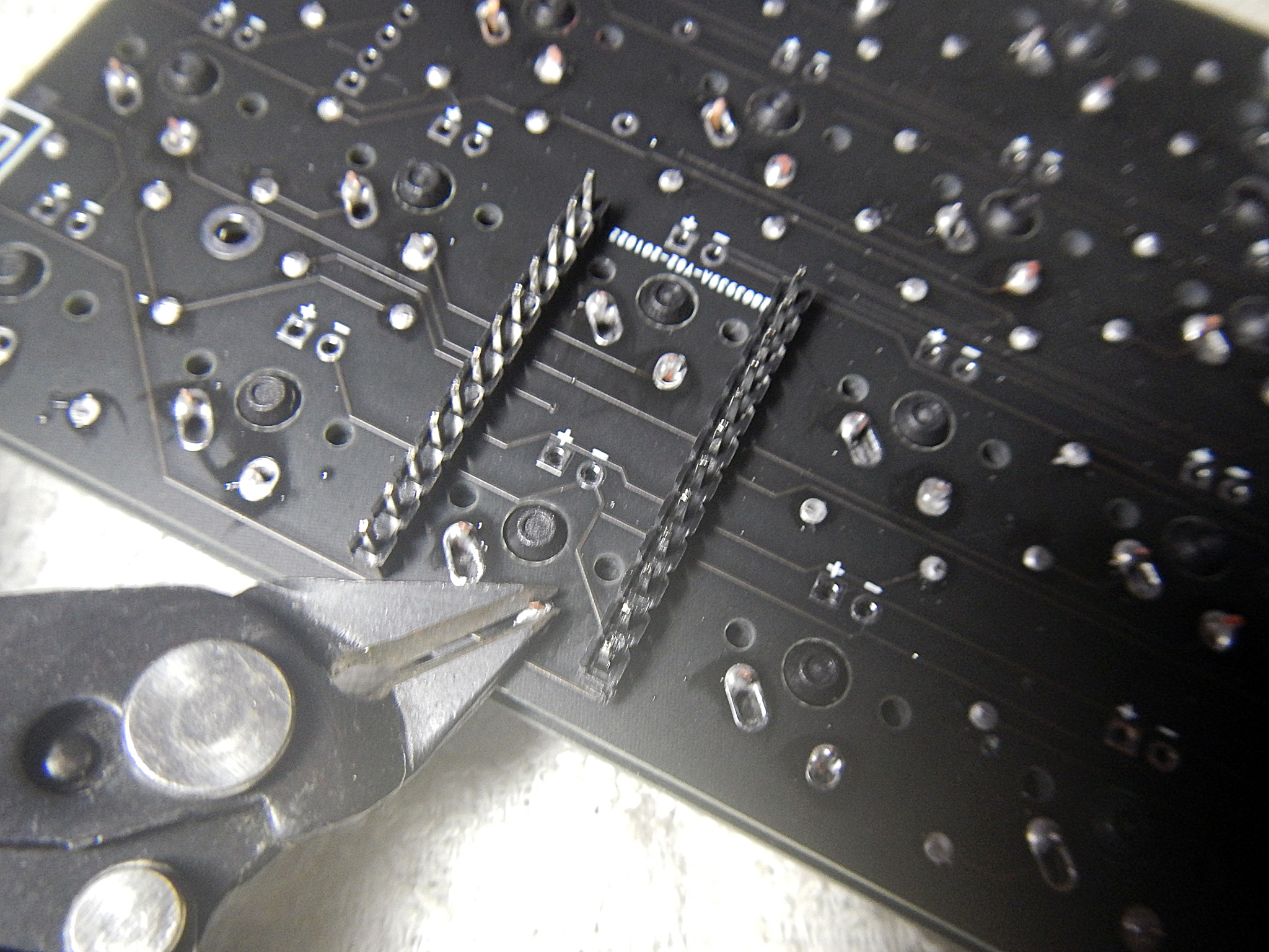
Solder pro micro pin headers and cut excess pins. Use eye protection glasses and cover the pins when cutting to prevent clipped pins from flicking.

Use brush to clean the PCB, inspect and make sure there are no trimmed pins and wires stuck on it.
Enclosure
Place the PCB assembly on the 3D printed casing. Insert screws on each holes and tighten. Since these casings are 3D printed, do not over tighten the screws to prevent loose threads. If this happens, a drop of super glue on the casing screw holes typically fixes it.

Update 202102060923: Soldering reset button.
Place solder on one pad. Using a tweezers, place one end of the button on the soldered pad. Re-heat solder to join with button's feet. Solder other side of button.
With all the components in installed, key caps can now be installed.
Comments
Post a Comment